Saturday, April 25, 2015

Baseline Demo

Hi guys!!!
We have our baseline demo in the following video:

p

We are going to work harder next week to build our final product. The have the following goals:
1. compact our sensing stuff to one box
2. smooth the servos

Eye Detection _ Update 3 _ April 14 - 25

We finally finished our first milestone demo!!! This past week has been nothing but lab for me. I know it's been about two weeks since my last post when I got the eye signal without the help of Biopac for the first time. I thought we could demo the next day, but I just couldn't get the signal processing circuit to work again. Maybe there were some bad connections on the breadboard somewhere. Maybe the amplifiers or the electrodes were worn out. Maybe my signal got wrecked just by someone walking around me (It's true! The electrodes can become that sensitive! I'll show you a video later.)

So I decided to solder my circuit onto a new board so that I don't need to worry about bad connections. Guess what? The new board couldn't work, not even the first stage of the circuit, the DIY instrumentation amplifier. When I set both input voltages at 0, it outputs a 5V high-frequency oscillation, which I couldn't explain. I need to a fine-tuned instrumentation amplifier!

So I waited for my AD620 to come for about a week. I followed some advice online and changed my circuit:
Coming out of the in-amp, the signal will go through a high-pass filter, a buffer, a second-order low-pass filter and a 60Hz "Twin-T" notch filter. 


Interesting thing about this circuit is that the drifting of the voltage level, which was a major problem for my previous circuit, is now gone. The voltage level will always stay around 0V (or any voltage I want), which is great for microcontroller sampling because it never goes out of the range of 0-5V. The downside of the circuit is that when the signal stays at some voltage level (e.g. when the user is staring at some angle), the output voltage decays to zero within maybe 100ms (half period depends on circuit design). So I would need to use some algorithm to recover the signal.
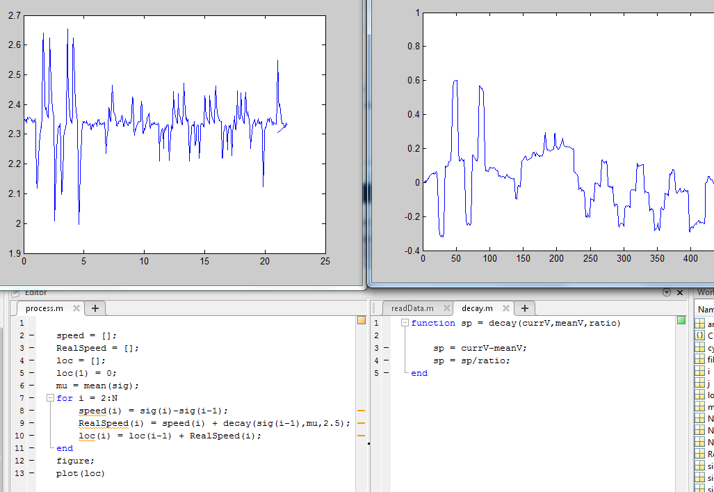
The up-left graph is the Vout of the circuit. When I roll my eyes to the right, Vout goes up. If we zoom in, we will see that the signal decays exponentially to the reference point after each peak, which means that at "free fall" (when Vin doesn't change), dVout/dt = C0 * (Vout - C1), where C0 is a constant that can be measured, and C1 is equal to the bias voltage I set. So in order to recover the signal, I can calculate dVout/dt, add back the "free-fall decay speed" of C0 * (Vout-C1) to get dVin/dt, and then do integral of dVin/dt to get the orientation of the eye. The up-right graph is the Vin recovered by algorithm above.

However, the algorithm doesn't work as nicely as above every time. See the following as an example:
The problem is that there's still the annoying drifting. Over about 10 seconds the random drift could account for as much as 50% of the output, which means that if the output changes by 100, the actual signal could have changed by any number between 50 to 100. This accuracy is unacceptable!

Also, there's the problem of choosing C1 (the reference voltage). Since there's the integral step in my algorithm, changing C1 by 0.01V would cause a massive drift of the output. It becomes really hard to let the micro-controller set the reference voltage correctly in the algorithm when it's real-time. How do i get that reference voltage, which is supposed to be constant but is actually different across different tests for unknown reasons? Average algorithm would be problematic when the signal is not symmetric.

So I decided to give up this circuit! This theory is beautiful, but there's always the distance between theory and reality.

New circuit: 

Not so different. Just that the high-pass filter and the buffer are gone. I tried this circuit and found that the drifting became really small in short period of time. Why much smaller than the circuit I used two weeks ago? I guess on that circuit I had too many cascaded RC low-pass filters, and they were cascaded without any buffer in between, so the cut-off frequency was actually much lower than what I calculated.(lowered to around 4Hz instead of the 16Hz that I intended) This would cause the drift to be relatively bigger than the EOG signal since drifting usually has a much lower frequency. And when I had 10 RC LPF cascaded like that, it's no surprise that I got a crazy 5V drift when the EOG signal is just about 200mV. With the new circuit, the cut-off freq stays at 16Hz. As a result, the drift and the EOG signal are "treated" quite equally. Over about a minute the drift could be around 0.1V - 0.2V when the signal is at 0.5V.

Although this is much better than before, I still need to work on this for the next week. So far I have tried some algorithms to eliminate noise and drifting of the HPF. For example I took the speed at each point and filter out all the low-speed points. This would filter out most of the noise and drifting, but due to the exponential decay property of that HPF circuit, some of the low-speed points play an important part in the recovery algorithm. Without them I will always under-compensate for the decay and thus the drift of reference. I guess it won't be such a big problem for the new circuit since it doesn't have that exponential decay property. I will put this part in the final post after I finish more testing on noise elimination, smoothing, and the final wrap-up. Check out Yifan's post for our milestone demo! It's really cool to see the robot's eyes move in the same way my eyes do!


Thursday, April 9, 2015

Eye Detection _ Update 2 _ April 3 - 9

This past week I've been working on building a circuit to process the EOG signal without using biopac. First of all, everyone has been telling me that I might get my eyes fried. The reason is that sometimes there might be large AC voltage in main power ground. So if I connect my eyes to the ground of main power, my eyes might be exposed to high AC voltage. The solution is easy, just keep the entire EOG circuit away from main power supply. I used batteries for my sensing circuit to power up the op-amps and the mbed. This mbed is going to use a zigbee chip to send the processed signal to another mbed that is connected to oscilloscope.

The first few days were not easy. I used a Duracell USB instant charger to power my circuit. Therefore my circuit was single-powered (0-5V), which was such a big mistake that I didn't realize at first. The circuit just wouldn't work, because the op-amps I was using were LM-741 and they had a input voltage range of power supply range minus 4V. Considering that my power supply from USB charger is not exactly 5V but around 4.5V instead, I only got an input voltage range of 0.5 volts! So I borrowed another charger to make the circuit split-powered.


The circuit is not very different from what I built for biopac. The V+ and V- electrodes signals will first go into an instrumentation amplifier. The output would be gain * (V+ - V-). Then this signal will go through a bunch of low-pass filters and amplifiers. Most of the AC noise will be filtered out and the DC component will be amplified to a much larger extent than the noise. Considering that the EOG signal would only be 3uV to 3.5mV, I set the DC gain at 20 and the AC gain of 10Hz signal at 1/2 for the instrumentation op amp.

It is not as easy as it seems. Sometimes the output voltage level drifts slowly from 0 to 5V and then from 5V to 0, which I just couldn't explain. Later I found some possible explanations for that:
1. My electrodes were slowly falling off of my face
2. Maybe I was just using some bad op-amps.
3. Voltage supply was not stable.

To eliminate these three possible causes for the problem, I...
1. wore a band to keep the electrodes on my face.
2. switched to LTC 1050 op amps from BioEngineering Labs. Compared to LM741 they seem to be much better for tasks that aim at small voltage and high accuracy.
3. Got chargers fully charged before using them. Put capacitors in parallel with power supply.

Also the noise seems to be much much bigger than the EOG signal. Fortunately they are at high freq and they seem to be repetitive. Therefore I did the following:
1. Add a bunch of low-pass filters. Alternatively I could just use a low-pass filter at a very low cut-off frequency. But then there comes the problem of low slew-rate, which means that the reaction of the system would be too slow. (When I set cut-off frequency at 1Hz, the half-period reaction time was about 1 second. Unacceptable!)
2. Use average algorithm in mbed to eliminate noise. I let the mbed calculate the average voltage of the all the measurements in past 15ms.

And after a long time of fine-tuning the circuit, I got this video:
You can see that there was a buggy moment in the video when the voltage level incorrectly stayed at maybe 5V. I still need to work on that. But anyway I've got my circuit working. And tomorrow Yifan and I are going to connect the sensing unit to the robotic unit. Something amazing is gonna happen!!

Eye Detection _ Update 1 _ Mar 27-29


Sorry for the late update! I'll try to remember what happened in the first three days. Basically I tested the biopac with electrodes around my eyes. The signal is very clean, though really small. So I built a very simple amplifier and low-pass filter. The amplifier has a gain of 10 and the filter has cut-off frequency at 30Hz. It worked really well. See video below:

In this video the signal corresponded to the horizontal movement of the eye. The center electrode acts like the ground. The other two are Vin+ and Vin-. According to the EOG theory, Vin+ minus Vin- will be proportional to horizontal orientation of the eye. 

Then I did a linearity test to see whether the signal is linearly dependent on eye movement. What I did was to stare at the red and blue circles from the left most one to the right most one, one by one. And then from right most one to left most one. Here's the circles I stared at and the signal I got:

Tuesday, April 7, 2015

Update 2: Camera orientation control 2.0 and Main Frame Control 1.0

Hi Everyone!

We have finished an updated version of our camera orientation control system. We can improved the design of the camera slot as well as the connection between servos and parts.


We also have designed a body frame , which has 2 degrees of freedom corresponding to the yaw and pitch of the robot head.


Plan for this week:
(1) work on Gyroscope sensing
(2) integration between eye sensing and control

Wednesday, April 1, 2015

1st Update: Camera Orientation Control

Hi Everyone!!!

This is the first update of our project. For the past week, we have been working on using EOG to sense eye orientation and the mechanical design of the robot eye. This post talks about the version 1 of the mechanical design:


We use 2 servos for each camera, the bottom one controls the yaw of the eye, while the side one controls the pitch of the eye. Such a design can ensure the camera is rolling like an eyeball, with its center fixed and all rotations are about the center.

We also used Adafruit 16 channel servo driver to expand the number of servos controlled by a single Raspberry Pi.

Details about this driver can be found via this link: https://learn.adafruit.com/adafruit-16-channel-servo-driver-with-raspberry-pi?view=all